
Power infrastructure / Troubleshooting
GPU Data Center Power Quality: Load Steps vs. Harmonics
A training job starts and the power dashboard flashes a warning. Before blaming harmonics—or changing a breaker—work out which electrical phenomenon actually occurred.
Sections in this article
Your new GPU row passes a steady-state power budget check. Yet when a distributed training job begins, electrical alarms appear. Is the problem current harmonics, a voltage sag or a protection-coordination issue? Those are different questions and they need different evidence.
High-density servers can create fast changes in demand, but that alone does not establish a voltage-quality violation or an imminent breaker trip. Start with the event waveform and a synchronized timeline. Do not change protective settings on the strength of a dashboard screenshot.
Four phenomena operators should stop mixing together
A sharp increase or decrease in current when compute activity changes. The impact depends on source impedance, UPS topology, aggregation and timing.
Record magnitude and duration. A sag can have many causes beyond GPU workload changes.
Nonlinear loads contribute harmonic currents. They require frequency-domain measurements, not merely a transient screenshot.
Switching and other disturbances may involve impulses or oscillation. Capture requirements depend on the frequency content.
IEEE 519-2022 addresses steady-state waveform distortion at the point of common coupling (PCC). Its limits are not a blanket 5% threshold for every rack PDU, nor a universal test for short-duration GPU load steps. Treat THD, TDD, RMS sags and high-frequency transients as related but separate observations.
Also avoid assuming GPUs cause every harmonic problem. The behavior depends on the entire server power supply, power factor correction, loading, UPS, distribution network and resonance characteristics. An unmeasured causal story can lead to an expensive, ineffective retrofit.
What to measure, and where
| Observed event | Measurement needed | First question |
|---|---|---|
| Server PSU resets near job launch | RMS voltage sag duration and magnitude at rack feed | Did input voltage cross the PSU's actual ride-through specification? |
| Warm transformer at moderate kVA | Load, temperature, current harmonic spectrum, thermal conditions | Is excess loss or ventilation contributing? |
| Repeated UPS alarms | UPS event codes, input and output waveforms, operating mode | Is it an input event, output event or protection configuration issue? |
| Breakers trip on starts | Trip-unit cause codes, waveform, coordination study, short-circuit model | Was there an actual fault or a legitimate protection response? |
| Distortion concern at utility connection | Current TDD and voltage distortion at PCC | Which IEEE 519 criteria apply to this system? |
IEC 61000-4-30:2025 defines repeatable methods for many power-quality parameters and measurement classes. It does not mean every compliant recorder captures all high-frequency switching behavior at 10 million samples per second. Specify waveform-capture capability separately for the event you are investigating.
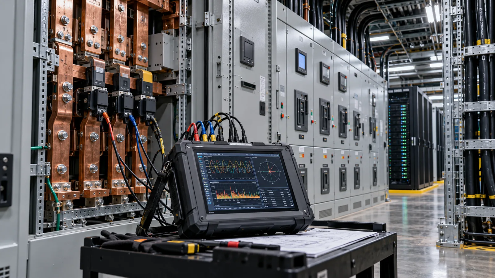
Install or temporarily place monitors at both ends of the suspected path when safe and feasible: near the cluster feed and farther upstream. Share a synchronized time source across workload scheduler, EPMS, UPS and monitoring systems. Without alignment, the apparent order of events can be misleading.
Illustrative investigation: did a GPU job trigger a trip?
This timeline is a hypothetical training exercise, not a documented real outage. Imagine a scheduled workload launch at 14:02 that overlaps a power event:
Scheduler: multiple workers launch; job ID and server group recorded.
Rack meter: real power rises; check meter aggregation interval before interpreting the slope.
PQ recorder: voltage dips to 92% of nominal for a brief interval.
Breaker event log: downstream protection operates; trip cause still to be determined.
The times illustrate the investigation process only. Correlation is the start of diagnosis, not proof that the GPU job fooled a relay. Engineers must check actual trip elements, instrument resolution, whether other feeders changed simultaneously, UPS behavior and any genuine short-circuit or ground-fault evidence.
When two systems show apparently simultaneous events, validate their clock synchronization. A server log timestamped in milliseconds is not necessarily accurate to a millisecond at the busbar. The right answer may come from protective relay event reports rather than the cluster application.
Mitigation should follow the measured cause
Review staggered job starts, manufacturer power-ramp specifications, UPS transient response and electrical headroom. Measure whether the change reduces the actual bus disturbance.
Perform a harmonic study using the measured spectrum and system impedance. Then evaluate filtering, equipment selection or ratings. Active filters are not a default answer to every alarm.
Require a qualified electrical engineer to examine fault records and coordination. Do not casually widen breaker trip settings or disable protection to accommodate workloads.
High neutral currents, overheating and unexplained bypass transfers are safety-relevant issues. They require site-approved electrical procedures and competent personnel. The goal of this article is to help frame the investigation, not to prescribe live switchgear operations.
Five questions before adding another GPU cluster
- Do server and rack power measurements cover idle, training ramp, synchronization and sustained peaks?
- Does the UPS vendor confirm the allowable step-load profile for this topology and operating mode?
- Are upstream transformers and cables assessed for harmonic heating and sustained current, not only nameplate kVA?
- Can meters and relay records reconstruct the last event with reliable synchronization?
- Is there a tested operational procedure to phase job starts without disrupting application requirements?
Bottom line: capture the disturbance, identify its category, locate it electrically and then choose corrective action. “GPU harmonics” is not a sufficient diagnosis.
Sources and further reading
Primary frameworks and reference materials. Engineering decisions require site-specific validation; legal classifications require assessment of the actual use case.