
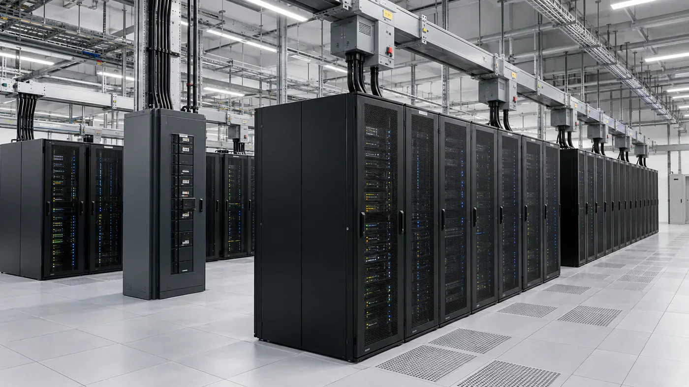
Busway and traditional PDU distribution can both deliver reliable power to data center racks. The real difference is where each architecture places cost, flexibility and operational complexity.
A traditional floor-mounted PDU and remote power panel architecture concentrates distribution into cabinets and then fans out branch circuits through cable. Overhead busway moves more of that distribution into a continuous bus above the white space, with tap-off boxes added where the load actually appears.
Neither approach is automatically better. A stable room with predictable rack positions can justify a very different distribution strategy from a rapidly changing AI hall where rack power may move from 20 kW to 80 kW or more within the life of the building.
Familiar, structured and often economical when the layout is stable.
Flexible tap-off locations make changes and density growth easier.
In spare circuits and cable pathways, or in the distribution system itself?
Start by defining what "PDU" means
Data center terminology can make this comparison confusing because "PDU" is used for more than one product.
At the rack, a PDU can mean a rack power distribution unit: the vertical or horizontal strip that provides outlets to IT equipment. That is not the PDU being compared here.
In facility power distribution, a floor-mounted PDU traditionally combines a transformer, panelboards or distribution sections, monitoring and branch-circuit distribution in a cabinet located in or near the white space. Remote power panels, or RPPs, can then extend that architecture by moving branch circuit breakers closer to rows of racks.
Usually floor-mounted and upstream of branch circuits feeding racks.
Moves breaker distribution closer to the rack rows without necessarily adding another transformer.
Supplies outlets to servers and other rack-mounted equipment.
Busway does not eliminate the rack PDU. It changes the path used to deliver branch power to that rack.
The architectures solve the same problem differently
Both systems need to take conditioned facility power and divide it into manageable branch circuits for IT loads.
Power is concentrated in cabinets and distributed outward through dedicated conductors.
A continuous overhead bus becomes the shared distribution spine.
Vertiv describes modern busway architecture in similar terms: an end-feed connected to upstream low-voltage switchgear, busway sections, and tap-off units with overcurrent protection. In suitable designs, the busway can replace floor PDUs and some conventional branch-circuit distribution.
The design implication is important. Traditional distribution creates more fixed connection points. Busway creates a reusable distribution path from which loads can be added, removed or moved.
Busway becomes more valuable as the room becomes less predictable
A traditional PDU architecture can perform very well when rack locations, circuit sizes and future demand are known with confidence.
The problem appears when the white space keeps changing.
Adding a new high-density rack to a cable-based system can require an available breaker, enough PDU or RPP capacity, a viable cable route, new conductors, labor, access above or below the room and sometimes a maintenance window.
A track-style busway changes the job. Eaton's PowerWave 2, for example, uses a continuous open-channel design that allows tap-off boxes to be positioned along the rail. The practical advantage is not that electrical design disappears. It is that the branch connection point can move with the load.
That difference can be worth very little in a static enterprise room and a great deal in a colocation, cloud or AI environment where deployment patterns change frequently.
Day-one cost and lifecycle cost can point in different directions
Busway is often sold on lower total cost of ownership, but the claim needs context.
A conventional PDU/RPP system can have a competitive day-one cost, especially where labor rates are moderate, circuit counts are known and the project does not expect frequent reconfiguration.
Vertiv notes this explicitly in its comparison of traditional and modern power distribution: conventional architecture can offer low day-one cost, while later circuit additions can become expensive because new cable routes and installation labor are required.
Busway shifts more cost into the initial distribution backbone and can reduce the incremental effort required to add later loads.
Future changes may require more cable, pathway work, breaker work and labor.
Future load changes can be made through additional or relocated tap-offs.
The correct comparison is therefore not: "Which system has the cheaper equipment quote?"
It is: "What does each architecture cost to install, operate and change over the expected life of this white space?"
A useful cost model separates fixed and variable distribution
I would divide both architectures into a fixed backbone and an incremental rack connection.
The busway case becomes stronger when many future circuits are expected, rack locations are uncertain or labor-intensive modifications would otherwise be frequent.
The traditional case becomes stronger when the final configuration is known and the facility is unlikely to change.
Do not use vendor savings percentages as universal project economics
Manufacturers publish comparisons showing lower installation cost, reduced labor and faster deployment for busway. Those studies can be useful because they expose the cost categories that should be compared. They should not be copied into every data center model as if the savings percentage were universal.
Starline, for example, publishes a head-to-head comparison of track busway and RPP architecture for a 28-rack row with A/B redundancy and states that busway produces a lower total project cost in that scenario.
That is evidence that the architecture can reduce installed cost under some assumptions. It is not evidence that every 28-rack room, every labor market or every redundancy design will produce the same result.
Reprice rail length, tap-off count, PDU/RPP count, conductor length, pathway, labor, monitoring and future modifications using the actual room geometry.
High rack density changes the economics
Rack density affects both the amount of power distributed and how valuable flexibility becomes.
A room designed around 8–12 kW racks can distribute a large IT load across many relatively small circuits. A high-density AI deployment can concentrate that load into far fewer racks, each requiring substantially larger branch capacity.
This creates two effects.
Higher current can increase conductor size, breaker rating and connection requirements.
The room may contain conventional, accelerated and storage racks with materially different power requirements.
Schneider Electric's 2026 grid-to-chip material reflects this broader shift toward scalable power distribution for AI infrastructure. Eaton likewise positions monitored busway as a way to manage rising AI power demand and changing rack configurations.
For a facility expecting density changes, I would model not only the maximum amperage of the busway but the operational problem of where that capacity can be tapped.
Our 20 kW vs 50 kW vs 100 kW rack density guide covers the downstream impact of those density steps in more detail.
Busway does not create capacity that does not exist
Flexibility can be misunderstood as unlimited expandability.
A 400 A busway remains a 400 A busway. Adding another tap-off does not create upstream UPS capacity, transformer capacity or thermal headroom.
The system still needs a load-management strategy.
Every new tap-off must be evaluated against bus rating, upstream protection, source capacity, phase balance and the design's redundancy assumptions.
This is where integrated metering becomes valuable. Modern busway can monitor the end feed and individual tap-offs, giving operators a clearer picture of what capacity is actually being used before another rack is connected.
Monitoring can move closer to the load
Traditional PDUs and RPPs can provide excellent branch-circuit monitoring. Busway can do the same while distributing meters across tap-off units.
Eaton's current PowerWave 2 platform, for example, supports source end-feed monitoring and branch-circuit monitoring at tap-off boxes, with protocols including Modbus, BACnet and SNMP.
The architecture question is less about whether monitoring is possible and more about where the measurement points live.
Many circuits can be measured in one distribution cabinet.
Tap-off level data can follow the physical location of rack loads.
For colocation operators, that can also support customer-level energy allocation when the metering accuracy and commercial architecture are appropriate.
Overhead distribution can free valuable floor and underfloor space
Floor-mounted PDUs consume white-space area. Underfloor branch cabling can consume plenum space in facilities that use raised-floor airflow.
Overhead busway moves a large portion of the distribution above the rack rows.
Vertiv identifies this as one of the weaknesses of traditional architecture: large amounts of underfloor cable can obstruct airflow and make future changes more difficult.
The value of reclaimed floor area depends on the room.
A modern slab-floor data hall with overhead network and mechanical services may care less about raised-floor congestion than a legacy room. But removing large floor PDUs can still simplify rack planning and reduce fixed obstacles.
Overhead space is not free either
Busway avoids some floor constraints by moving the distribution problem overhead. That space may already be competing with cable tray, chilled water or liquid-cooling piping, containment structures, lighting, fire protection and structural bracing.
High-density AI rooms can make that coordination harder, not easier.
A successful busway design therefore needs a real overhead coordination model rather than the assumption that rails can simply be placed above every row.
Installation speed is one of busway's strongest practical advantages
Conventional branch distribution requires many repetitive field operations: pull conductors, identify routes, terminate both ends, test circuits and manage the physical accumulation of cable.
Busway is more prefabricated. Rails are installed as a distribution spine, then tap-offs are fitted where loads are required.
Eaton describes its track-style system as tool-less at the tap-off connection and emphasizes rapid installation and reconfiguration. Other products use different connection mechanisms, so the exact maintenance procedure needs to be confirmed for the selected system.
The schedule advantage becomes most valuable during phased deployment. The room can receive its backbone early and add rack connections as IT equipment arrives rather than installing every branch circuit on day one.
Traditional PDU architecture still has strong use cases
Busway's flexibility can make the traditional alternative sound obsolete. It is not.
Floor-mounted PDUs and RPPs remain useful when:
- rack locations and loads are stable;
- the project has a well-defined final circuit schedule;
- existing staff and maintenance procedures are built around the architecture;
- the facility is being expanded within an installed PDU/RPP standard;
- overhead space is heavily constrained;
- branch distribution needs to be concentrated in known service points;
- the expected rate of moves, adds and changes is low.
There is also value in familiarity. A theoretically flexible system can be a poor operational choice if the site team cannot maintain it safely or if the selected product creates a proprietary spare-parts problem.
Transformer-based PDUs can create an efficiency penalty
Traditional data center PDUs historically performed two jobs at once: voltage transformation and branch distribution.
When a design no longer needs local transformation, keeping a transformer-based PDU purely because it is familiar can add conversion losses and heat.
Vertiv highlights this issue in its busway white paper, noting that large transformer-based PDUs generate waste heat that must then be removed by the cooling system.
This does not mean that eliminating a PDU always improves efficiency. The system still needs the correct voltage, grounding, isolation and protection architecture. The comparison only becomes valid after those electrical functions are accounted for elsewhere.
Our 208V vs 415V data center power guide explains why voltage architecture and downstream current are linked.
A/B redundancy works with either architecture
Data center redundancy is not a unique property of busway or PDU distribution.
A dual-corded rack can receive an A feed and a B feed from two independent distribution paths in either architecture.
Separate branch circuits feed the two rack PDUs.
Independent tap-offs feed the two rack PDUs.
The real design questions are whether the two paths share upstream sources, physical routes, support structures or maintenance dependencies that could create a common failure.
Redundancy should be traced from utility and generator architecture all the way to the rack, not inferred from the existence of two whips above the cabinet.
Maintenance changes when the distribution system becomes modular
Traditional distribution concentrates a large number of breakers in a smaller number of cabinets. Busway distributes more branch components throughout the room.
That affects inspection, spare strategy and maintenance procedures.
Busway operators need to manage tap-off compatibility, breaker families, mechanical connection condition and the approved method for adding or removing units. A system designed for safe tool-less installation still requires the operator to follow the manufacturer's energized-work rules and the site's electrical safety program.
PDU/RPP systems create a different maintenance concentration: fewer distribution locations, but potentially larger groups of branch circuits affected by cabinet-level work.
Busway can reduce stranded branch capacity — but not automatically
A conventional RPP may have spare breaker positions that remain unused because the racks near that panel do not need them, while another part of the room runs out of circuit capacity.
Busway can make connection points more fungible along the rail.
That can reduce one form of stranded capacity: unused physical breaker locations in the wrong place.
It does not eliminate electrical stranding. A lightly loaded tap-off in one section does not help if the upstream rail, source or redundancy block is already at its design limit.
Good capacity planning therefore needs both physical flexibility and electrical headroom.
A simple 30-rack example shows where flexibility starts to matter
Consider an illustrative room with 30 dual-corded racks.
In a traditional design, the team can reserve panel positions and pathways for the ten future racks. That is a valid strategy, but the project must decide where those future circuits are likely to land.
With busway, the project can install enough rail and source capacity for the expected growth while delaying more of the final branch configuration until the racks are actually deployed.
The example does not prove that busway is cheaper. It identifies the uncertainty for which busway is being purchased.
Brownfield retrofits can favor either solution
Busway is attractive in retrofits because it can create a new overhead distribution layer without rebuilding every existing branch circuit.
But brownfield conditions can also work against it.
Low ceilings, congested trays, structural limitations, active cooling pipework and limited shutdown windows can make installation difficult. An existing PDU/RPP infrastructure with spare capacity may be cheaper to extend than to overlay with a new system.
I would therefore survey three things before assuming busway is the retrofit answer:
- available overhead route and support structure;
- actual spare upstream electrical capacity;
- the expected number and size of future changes.
If the room will receive only four new racks, a large new distribution spine may never recover its initial cost.
How I would compare busway and PDU for a new data hall
How I would build the cost comparison
- Define the same upstream boundary for both alternatives.
- Use the same rack count, rack power profile and A/B redundancy.
- Price floor PDUs, RPPs, breakers, cable, conduit or tray and installation for the traditional option.
- Price end feeds, busway rail, supports, tap-offs, monitoring and rack whips for the busway option.
- Include the white-space area consumed by cabinets where it has commercial value.
- Include overhead or underfloor coordination and support requirements.
- Model at least one future expansion or rack-density change.
- Add maintenance, spare parts and monitoring costs.
- Compare installation schedule and any required outage windows.
- Test the result against a low-change and high-change operating scenario.
So is busway better than PDU distribution?
Busway is usually the stronger architecture when the white space is expected to change, rack density is high or uncertain, floor area is valuable and the operator wants to add branch connections without repeatedly installing new home-run circuits.
Traditional PDU and RPP distribution remains a strong solution when rack locations are predictable, the circuit schedule is stable, existing standards favor that architecture or the project does not need to pay for flexibility it is unlikely to use.
The useful distinction is not modern versus old.
It is fixed versus adaptable.
A PDU/RPP architecture commits more of the final branch distribution earlier. Busway moves part of that commitment later, when the rack locations and power requirements are known.
In a 2026 data center market increasingly shaped by AI loads, phased deployments and rapid changes in rack power, that option value can be significant. But it should still be priced against the actual room, actual labor market and actual operating plan rather than assumed from a vendor percentage.
Sources and research notes
- Vertiv — Optimizing Data Center Power Distribution Through Innovative Busway Design . Used for traditional PDU/RPP versus modern busway architecture, scalability, cabling and transformer-loss context.
- Eaton — PowerWave 2 Busway . Used for current track-style busway design, tap-off flexibility, monitoring and communications context.
- Eaton — Data Center Busway Overview . Used for white-space and grey-space busway architecture context.
- Schneider Electric — From Grid to Chip: Scalable Power Distribution for AI Data Centers . Used for 2026 AI power-distribution context.
- Schneider Electric — Busway Product Architecture . Used for current busway rating and application context.
- Vertiv — Floor-Mount Data Center Power Distribution . Used for current floor-mounted PDU and distribution-product context.
- Starline — Track Busway vs Remote Power Panels . Used as a vendor worked example of installed-cost comparison. The vendor's savings claim is not treated as a universal market benchmark.